




The Use of Ball Grid Array Rework Stencils
Nov 12th 2026
Submitted as I-Connect007 Knocking Down the Bone Pile Column – Part 16
By Nash Bell
Overview
Ball grid array (BGA) devices provide high I/O density and compact package size, but their hidden solder joints make rework challenging. Successful replacement depends on controlling site preparation, solder deposition, placement and reflow.
One of the simplest tools in that process is the rework stencil. I view it as a process-control tool rather than simply a way to put paste on a board. Its design affects solder volume, print consistency and sometimes component alignment.
When Should Solder Paste Be Used?
A question that comes up frequently is whether solder paste should always be printed on the PCB before placing a replacement BGA. At BEST, we do not automatically apply solder paste for every standard BGA placement. For most BGAs with collapsible solder balls, our normal process is to use an appropriate tacky flux and rely on the solder already present on the component to form the joint during reflow. We typically add solder paste when a customer specifically requests it or when there is a clear process reason to do so.
There is not one universal rule requiring paste for every BGA rework. The method depends on the package, land geometry, customer requirements and qualified process. My preference is not to add another process variable unless it provides a clear benefit; paste printing introduces stencil thickness, aperture size, alignment and deposit volume as additional variables.
Solder Paste Volume
When solder paste is used, the objective is to deposit a controlled and repeatable volume, not simply to add more solder. Too much paste can increase the risk of solder balls, bridging or inconsistent collapse, while too little can contribute to insufficient joints. The PCB site should first be prepared so the pads are reasonably flat and free of excessive residual solder.
For standard BGA rework, the stencil aperture diameter will generally be based on the PCB pad size, leaving stencil thickness as the main variable used to control paste volume. A simple rule of thumb is that stencil thickness should be about one-third of the aperture diameter. For example, if the aperture is 12 mils in diameter, a stencil around 4 mils thick is a reasonable starting point. As the aperture diameter gets smaller, the stencil generally needs to become thinner so the paste can release cleanly and consistently.
In practical terms, finer-pitch BGAs with smaller pads usually require thinner stencils, while larger-pitch devices can tolerate thicker stencils. The goal is to provide enough solder volume without making the stencil so thick that paste release becomes inconsistent or bridging risk increases.
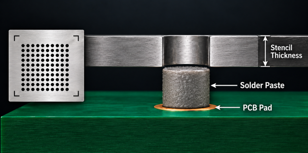
Fig. 1: Stencil thickness controls the height of the solder paste deposit while aperture diameter is generally based on the PCB pad size.
BGA Rework Stencils
Three common approaches are miniature metal, removable adhesive-backed and stay-in-place stencils. Each can produce good results, but they behave differently on a real assembly. The choice usually comes down to access, quantity, pitch and how much alignment assistance is needed.
Mini Metal Stencils
Miniature metal stencils are common and work well when there is sufficient access around the rework location. Their main advantage is durability: they can be cleaned and reused for repeated rework of the same device.
In practice, however, they require good physical access to the site and consistent contact with the PCB surface. Nearby components can make positioning and printing more difficult on densely populated assemblies. The stencil also needs to sit flat against the board; any distortion, bowing or uneven contact can affect paste deposition and produce inconsistent volume across the array. Metal stencils work well when there is adequate room and support, but they are not always the most convenient option for tight rework locations.
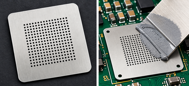
Fig. 2: Miniature metal BGA rework stencil used for manual solder paste printing.
Removable Stencils
Removable adhesive-backed stencils are the option we use most commonly at BEST for standard BGA rework. Because the stencil adheres directly to the PCB surface, it maintains good contact with the board and helps promote consistent solder paste deposition across the array. After printing, the stencil can be peeled away cleanly without leaving adhesive residue, and after component placement there is no visible indication that a stencil was used during the rework process.
Their main limitation is that they are generally intended for single use. Care is also required with very small apertures and fine-pitch arrays. When the stencil is removed, some solder paste can remain attached to the aperture walls and be lifted away from the PCB, reducing the deposited volume. This makes stencil thickness, aperture size, paste release and removal technique increasingly important as pitch becomes finer.

Fig. 3: Removable adhesive-backed BGA stencil being peeled from the PCB after printing.
Stay-in-Place Stencils
Stay-in-place stencils can provide one of the most consistent methods for controlling solder paste deposition during BGA rework. Because the stencil is held firmly against the PCB with a high-temperature adhesive and remains in place through the reflow cycle, it maintains alignment and helps keep the solder paste separated between adjacent pads. This can reduce the likelihood of bridging or shorts during placement and reflow.
Another advantage is that the stencil does not need to be removed after printing, eliminating the possibility of disturbing or lifting some of the paste during stencil removal. The tradeoff is that these stencils are single-use and remain on the assembly after rework. Once the BGA is installed, the stencil can still be visible beneath the edge of the component when viewed from the side. Where cosmetic appearance or leaving no visible indication of rework is important, a removable stencil may be preferred.
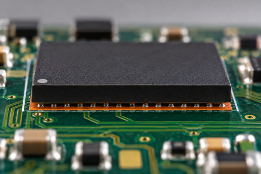
Fig. 4: Side view of a BGA installed over an orange stay-in-place stencil, which remains beneath the package after reflow.
Conclusion
Stencil selection can have a significant effect on repeatability. Mini metal stencils offer durability and reuse when the site is accessible. Removable stencils are my preferred option for many standard BGA repairs because they sit flush to the board and leave no visible evidence after removal. Stay-in-place stencils provide excellent control of paste deposition and alignment but remain visible beneath the finished component.
The practical lesson is not that one stencil is best for every job. Start by deciding whether solder paste is needed at all. If it is, choose the stencil around the board geometry, pad size, pitch and the needs of the specific rework. Good BGA rework depends on controlling solder volume, alignment and heat; the right stencil simply makes those variables easier to manage.