



Hot Air vs Infrared Printed Circuit Board Rework
Posted by Nash Bell on Jul 28th 2026
Overview of PCB Rework
Component rework is the controlled process of removing, replacing, repositioning, or repairing electronic components on an assembled printed circuit board. Rework may be required because of component defects, incorrect placement, soldering defects, engineering changes, or damage identified during inspection or testing. A successful rework process uses controlled heating, soldering, cleaning, handling, and inspection techniques to restore the assembly while minimizing thermal and mechanical stress to the PCB and surrounding components.
Common Rework Methods
Although several methods may be used to rework printed circuit boards, hot-air and infrared systems are among the most common for area-array and surface-mount components. Hot-air rework directs heated air or nitrogen through a nozzle to concentrate heat around a specific component. Infrared rework uses radiant energy to heat the component and surrounding area without forced airflow, often providing broader heat exposure.
Both types of systems commonly include bottom-side preheating, adjustable board supports, component alignment or placement features, and thermocouple monitoring. These controls help develop and repeat a thermal profile that brings the solder joints to reflow temperature without unnecessarily overheating the component, PCB, or adjacent parts.
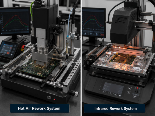
(Fig. 1: Hot air rework system and IR rework system for removal of electronic devices)
Both hot-air and infrared systems are accepted rework methods, but neither is the best choice for every assembly. The appropriate method depends on factors such as component construction, PCB thermal mass, surrounding component density, surface finishes, accessibility, and production requirements. The following sections compare the advantages and limitations of each method.
Pros: Hot Air
Targeted Heat Exposure – Hot-air rework is a widely used and accepted method for reworking ball grid array (BGA) packages because it provides localized heating through a targeted nozzle. Nozzles are designed to fit closely around the component perimeter, helping focus heat on the target package while improving access in densely populated assemblies and limiting thermal exposure to nearby components, connectors, and other heat-sensitive features.
Less Affected by Surface Finishes – Another benefit of hot-air rework is its ability to accommodate component packages made from a wide variety of materials, colors, and surface finishes. Packages with higher thermal mass, such as ceramic or metal packages, generally require more time and energy to reach reflow temperature than plastic packages. However, hot-air heating is typically less affected by differences in surface color, emissivity, and reflectivity than infrared heating.
Repeatable Process Control – Hot-air rework systems provide repeatable process control by allowing key variables such as nozzle temperature, airflow, bottom-side preheat, and profile timing to be adjusted and documented. Thermocouples can be used to monitor actual temperatures at the component, solder joints, PCB surface, and underside of the board throughout the heating cycle. Once a successful thermal profile is developed, the same process parameters can be saved and repeated on similar assemblies. This improves consistency while reducing the risk of overheating, insufficient reflow, and unnecessary thermal exposure.
Pros: Infrared
Broad, Uniform Heating – Infrared rework systems apply radiant energy across a wider area, which can help heat the component and surrounding PCB more gradually and evenly. This broader heating approach may reduce steep temperature differences across large components or high-thermal-mass assemblies when the process is properly profiled.
Airflow-Free Rework – Because infrared systems transfer heat without forced air, they eliminate the risk of airflow disturbing small, lightweight components near the rework site. This can be beneficial on densely populated assemblies containing chip components, fine-pitch devices, or other parts that could shift during reflow.
Reduced Dependence on Custom Nozzles – Infrared systems can accommodate a wider range of component sizes and shapes without requiring a dedicated nozzle for every package. This may reduce setup time and tooling costs, particularly for low-volume work or assemblies containing unusual component geometries.
Faster Heating for Production Work – Infrared systems can heat the component and surrounding PCB more quickly by transferring radiant energy across a broad area at the same time. This can shorten cycle times and improve throughput for repeat production work, particularly when the assembly has consistent materials, surface finishes, and thermal characteristics.
Cons: Hot Air
Risk to Adjacent Components – Although a targeted nozzle limits the heated area, escaping airflow and radiant heat from the nozzle can still affect nearby components, connectors, or plastics. Improper shielding, nozzle selection, or airflow settings may cause adjacent solder joints to reflow or small components to shift.
Custom Nozzle Requirements – Hot-air rework often requires a nozzle sized closely to the target component. Unusual package dimensions or crowded layouts may require custom tooling, increasing setup time, cost, and lead time before rework can begin.
Localized Thermal Stress – Concentrated top-side heating can create a temperature difference between the component area and the rest of the PCB, particularly when bottom-side preheat is insufficient. Excessive ramp rates or uneven heating can increase the risk of PCB warpage, package warpage, delamination, or damage to the rework site.
Cons: Infrared
Affected by Surface Properties – Infrared heating is influenced by the color, emissivity, reflectivity, and finish of the component and PCB surfaces. Dark or matte materials may absorb energy quickly, while shiny metal lids, exposed copper, or light-colored surfaces may reflect energy and heat more slowly, making temperature control less predictable.
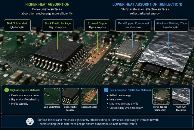
(Fig. 2: PCB and component surface properties influence infrared heating; dark, matte materials generally absorb radiant energy more readily, while shiny metallic surfaces reflect more energy and may heat more slowly.)
Less Localized Heat Control – Infrared systems typically heat a broader area than a fitted hot-air nozzle. This can expose nearby components, connectors, and the PCB laminate to additional heat, particularly when the rework site is densely populated or close to temperature-sensitive materials.
Line-of-Sight Heating Limitations – Infrared energy primarily heats surfaces directly exposed to the emitter, while raised components, shields, and surrounding features can block or redirect the energy. This may create uneven heating or require additional shielding and thermal profiling to ensure the solder joints reach reflow temperature without overheating exposed surfaces.
Importance of Thermal Profiling
Regardless of whether hot air or infrared is used, a validated thermal profile is essential to ensure the solder joints reach reflow temperature without overheating the component, PCB, or surrounding parts. With hot-air systems, the profile focuses heavily on nozzle temperature, airflow, bottom-side preheat, and the temperature difference between the component and PCB. Infrared profiling requires additional attention to surface color, emissivity, reflectivity, component height, and line-of-sight exposure because these factors can cause different areas to absorb radiant heat at different rates. Thermocouples should be placed at critical locations to confirm actual temperatures rather than relying only on the machine’s programmed heater settings.
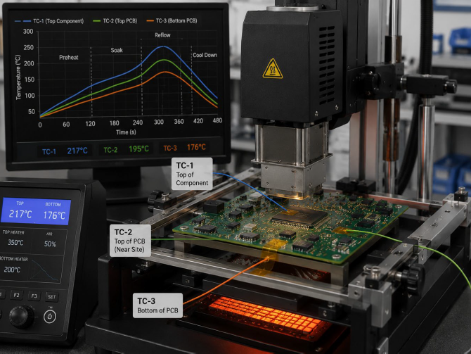
(Fig. 3: Thermal profiling during BGA rework uses thermocouples at critical locations to verify component, PCB, and bottom-side temperatures throughout the heating cycle.)
Selecting the Appropriate Rework Method
Both hot-air and infrared systems can produce reliable BGA rework results when properly applied and thermally profiled. Hot air is generally preferred when localized, predictable heating is required, while infrared may be advantageous when broader, airflow-free heating or improved production efficiency is beneficial. The most appropriate method depends on the component construction, PCB thermal mass, surrounding layout, surface finishes, and production requirements. Ultimately, successful rework depends less on the heating technology itself and more on controlled heat delivery, accurate temperature monitoring, and a repeatable process.
Written by Nash Bell, President of BEST Inc