ESD. MSD and Mechanical Component Handling
The issues related to handling components from an ESD and MSD perspective as well as making sure the parts are handled properly from a mechanical standpoint are important in ensuring the highest possible yield. BEST can provide these other services.
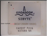
BEST offers accurate laser marking of reballed BGAs. Laser marking can incorporate any size fonts or graphic images as small as 5x5 mm.
If the devices were initially purchased having lead-free alloy balls and we have re-attached leaded balls, we suggest the following symbol be LASER marked (E0).
If the devices were initially purchased having tin-lead alloy balls and we have re-attached lead-free balls, we suggest the following symbol be LASER marked (E1).
 Laser marked and reballed BGA
In addition to this permanent marking “paint dot markings” are used to indicate visually that the component has been reballed. Epoxy ink dot markings can be done to comply with Mil-STD-130, Mil-STD-883, and or A-A-56032.
Automated optical testing systems are used to analytically confirm the quality of the reballing of the component. By using a high speed camera and specialty lighting partners for each placed ball can be confirmed including: small ball, large ball, FOD presence, solder bridging, ball diameter and z height/ball coplanarity. The components are placed into a fixture or on tape and reel and the machine is programmed to inspect the reballed devices. Set-up and programming time as well as processing time are a part of these services.
For smaller lot sizes this maybe confirm by 10X magnification testing per the guidelines found in the IPC-7095 document.
Some of the industry standards include process verification and control by performing analytical testing to verify that the reballing process is in control.
Some of the more common tests are listed below:
Ball ShearAccomplished per JESD22-B117 helps determine the mechanical strength of the bond created between the solder ball and the pad by measuring the shear force that it takes to remove the ball. |
XRF TestingConfirms the alloy composition of the reballed component in accordance with for alloy composition and finish thickness testing per JESD 213. |
Acoustic MicroscopyThis technique is a non-destructive microscopic imaging technique which can be used to test the internal structure of objects by using high-frequency sound waves. It can be used to perform hermeticity testing (fine and gross leak) per MIL-STD-883 or per testing found in J-STD-035. |
Ionic ChromatographyThis is a cleanliness confirmation test to ensure that ionic species, which may hasten dendritic growth as outlined in J-STD-001. |
SolderabilityThis testing can confirm that the solderability of the reballed component meets J-STD-002. |