 StencilQuik™ ReballingThis BEST developed BGA reballing technique is the designed for speed and fast turn-around of small to medium volume quantities. It is used as other high volume tooling and fixturing is being designed and fabricated for higher volume reballing projects. The stencils are custom designed and fabricated inhouse at BEST for your patterned device on one of the BEST lasers. After applying flux to the bottom of the part, a polyimide stencil corresponding to the pattern/size of the balls is aligned over the part pads. The properly sized solder balls are then poured into the apertures with the fixture keeping the StencilQuik™ stencil affixed to and aligned with the part. The assembly is then reflowed, cleaned and inspected. It is the most time-consuming of the BGA reballing techniques used at BEST.
This technique is one that is straightforward and is used when a moderate number of the same part pattern reballing is required. The tooling and stenciling can accomodate several BGA reballing cycles. Many times since the tooling is created in house the lead time for customers is advantageous.
![]()
![]()
![]()
![]()
![]()
![]()
![]()
![]()
![]()
![]()
![]()
![]()
![]()
![]()
![]()
![]()
![]()
![]()
![]()
Prepare Device Preparing your device for reballing Preparing your device for reballingThe dressing of the pads can be done by one of several methods. The methods for the removal of solder (deballing) from the package include the use of solder wick and a soldering iron, solder vacuum tools or machines or solder pot techniques. The solder vacuum process has less chance of damaging the pads while being somewhat slow. The braid technique, while faster, can lead to lifted pads or otherwise damaged solder mask areas if not done properly or with the right size of wick. The use of a solder pot requires the ability of the equipment to maintain temperature while making sure that you know the type of alloy that the balls are made from in order not to contaminate the solder pot. After the balls have been removed and the site prepped it is good practice to leave some solder on the pads in order to make reballing easier. Clean the package with the proper cleaning agent based on the flux chemistry used. This should be completed immediately after the balls have been removed as this will make cleaning up of the flux residue easier. Be sure to inspect the solder mask in between the pads to insure that its integrity has been maintained. This inspection should be performed using a stereo microscope or other optical inspection tool. Make sure all of the solder balls have been removed. |
Choose Reballing MaterialsMake sure that the fixtures and the miniature stencils are the correct pattern and pitch, in useable condition and clean. Insure that the proper solder alloy and ball size has been chosen. Insure that the properly-specified "tacky flux" has been chosen. |
Apply Flux to Part
|
Loading of Solder Balls using a StencilQuik™ Stencil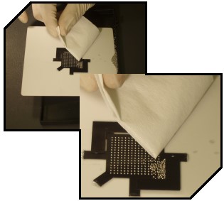 The "loading up" of solder balls onto the underside of the device is done using a polyimide stencil. The stencil is aligned with the pads on the bottom of the device and solder balls are poured into the various apertures of the stencil using a mechanical fixture which "captures" the excess solder balls. An ESD-safe, clean soft bristled brush is used to assist the "sweeping" of the balls into the apertures. Excess balls are collected in the "catch basin" portion of the fixture which allows the solder balls to be later poured back into original solder ball container. |
|
CleaningThe reballing process used by BEST includes the use of water soluble "tacky flux" prior to replacing the balls back onto the component . This water soluble flux insures that the sites are properly prepared and that wetting action occurs on all the pad surfaces. While these water soluble processes have many processing benefits, their more aggressive nature and their potentially harmful by-products must be cleaned off the BGA or CSP substrate after having the solder ball attached. BEST implements a rigorous cleaning process to remove residues from the underside of the device. This insures that no matter the end use of the reballed device, they are sent back cleaned and with the confidence that there will not be any product reliability issues related to ionic contaminants or residues left on the BGA/CSP after reballing by BEST. In order to insure the level of cleanliness is obtained with the BEST cleaning processes, BEST cleans reballed devices to a programmed cleanliness level. Our closed-loop cleaning system washes devices to a pre-selected resistivity level using only DI water. During the wash cycle, the water is continuously purified by a series of filters. Each batch of reballed devices cleaned in this manner comes with a cleanliness document verifying that the parts meet a given ionic contamination level equivalence. IPC J-STD-001 specifications for ionic cleanliness are met for all cleaned devices. |
Ionic Cleanliness TestingAn ion chromatograph (IC) is the most common tool for precision testing of device cleanliness. This method can quantify and identify specific ionic species that are present on an electronic device. The most common test method followed is the IPC TM-650 2.3.28. The device is placed into an ionically-clean bag (e.g. Kapak), and is immersed in an extract solution of 75% isopropyl alcohol (IPA) to 25% de-ionized water. It is important to be sure that the sampling procedures do not introduce any ionic contaminates. The PCB is extracted in the solution for one hour at 80 degrees centigrade, the resulting extract is then injected into the ion chromatograph. The IC then separates and detects each individual ion for which it was calibrated. Click here to see an Ionic Cleanliness Testing Report (PDF). |
|
|
|


 Tacky flux is now spread onto the bottom of the part after being dispensed via a syringe. The flux should have the following characteristics:
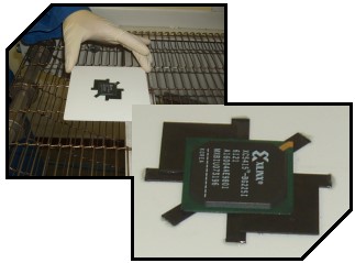 Baking
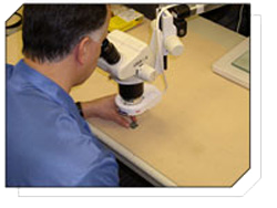 Inspection
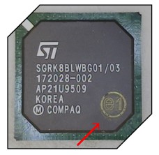 Marking