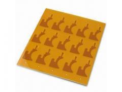
Laser Machining of Coverlays
 In “flex” or flexible printed circuit board manufacturing, a flex circuit coverlay is used to encapsulate and protect the external circuitry of a flexible circuit board. Think of it is solder mask for a flex circuit except that it has an added element of flexibility and durability it provides to the flexible circuit board.
The coverlay itself consists of a solid sheet of polyimide with a layer of flexible adhesive that is then laminated under heat and pressure to the circuit surfaces. The required component feature openings are mechanically created using drilling, routing, or laser cutting, Typical coverlay thickness is 0.001" polyimide with 0.001" of adhesive. And then either 0.0005" to 0.002" thicknesses are available but only used as needed to meet specific design requirements.
Coverfilm or coverlay is used to encapsulate and protect “flex” external circuitry allowing it to withstand extreme vibration, temperature and other harsh environments. The easiest way to modify this “solder mask” of flex circuit boards (comparing it to its rigid board cousin) is via laser machining.
Laser machining is done during the pre and post preparation of the coverlay. Prior to coverlays being aligned and laminated on production flex panels, a laser routs or drills the coverlay for the flex circuits feature openings. After the coverlay has been laminated a laser sciving process (see below) can be used to remove the coverlay to expose underlying circuitry or pads without any damage to the copper. Coverlays which are attached with adhesive can exhibit “squeeze out” of the adhesive on to a pad land after the laser machining process. Good design practices recommend that the access openings be large enough to allow for squeeze-out while still providing a good solder fillet that will meet IPC-A-610 standards. To eliminate squeeze out issues in an area, laser skive the coverlay pad exposures or fingers post coverlay lamination.
Coverlay skiving ( a selective ablation process that can completely obliterate one material with or without affecting an underlying material) is used to form openings smaller than mechanical drilling or routing or openings too small to accurately align during lamination. Window skiving is also done on floating contacts (fingers) prior to tinning, plating or soldering.
File Requirements
CAD system integration and custom file converters enable flexible, laser manufacturing from user-provided data. Although most file types are accepted, the preferred file types are Gerber, DXF, or other 2D formats. In most cases, non-scaled data is required as BEST technicians will make the appropriate offsets and properly scale in order to meet part dimensions.
Typical Coverlay Routing & Skiving Tolerances for BEST lasers
|
Positional |
(4um) |
|
Dimensional |
(5um) |
|
Smallest holes |
(20um) |
|
Cutting line width |
(25um) |
|
Depth |
Application Dependent |
Call BEST today to discuss your laser coverlay machining application.


