


Call us Now! 1-847-797-9250
BEST soldering geeks enable electronics companies to be more effective through professional instruction, tools and taking secondary assembly projects off your plate
BEST soldering geeks enable electronics companies to be more effective through professional instruction, tools and taking secondary assembly projects off your plate
A strong supplemental tool to XRAY, a endoscopic inspection tool, allows hidden solder joints or joints that are in close proximity to other nearby parts to be inspected and characterized. BEST has the capability to inspect and troubleshoot process defects through the use of this tool.
 Inspection System
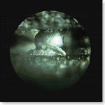
While there are several destructive methods (SEM or pull strength testing) for detecting the presence of defective solder joints underneath sections of grid array packages, the endoscopic inspection tool serves a unique and useful purpose. A solder joint can prematurely fail due to the shear stresses caused by the Coefficient of Thermal Expansion mismatch between the ceramic material and the substrate is substantial. The ability to "see" whether the reflow process delivers a defective or a target joint condition (see figures below) can be accomplished with this inspection tool. While this joint would pass a test for shorts and opens during electrical test, life cycle tests would reveal a different story.
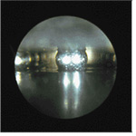
One of the major benefits of using such an inspection tool is its ability to "see" underneath the grid array and the surface of the individual solder balls. Clues to the quality of this joint include its texture, uniformity, smoothness, color and brightness and surface characteristics. A poor solder joint with micro cracks on its surface could be "seen" with the endoscopic inspection tool but would not show up on XRAY. Flux residue spread between the balls underneath the array can lead to bridging of conductive particles and a shorting between pads. This can be discovered with the use of this inspection device.
 Lead free solder lift off
The endoscopic inspection system with its accompanying image capture software can be used to gauge a go/no-go decision in terms of the quality of the solder joint. By using window overlays of good/bad reference pictures the joints can be inspected as part of the quality control process. Critical ball dimensions can be measured in terms of their standoff heights, wetting angles, pt-pt distances in order to confirm the "quality". These images can be captured and trended for capability studies or failure analysis. These measurements also add to the objectivity of the soldering process. Over time a large database containing the various critical process parameters involving soldering (flux, paste temperature profile, etc) can be stored and subsequent troubleshooting becomes faster. Component and equipment suppliers as well as end customers can be shown these images in order to effectively communicate the status of the process development.